
-
Phone: +91 (0251) 220 6495
-
Email: info@pnsco.in
-


Quick Links
Our Infrastructure
Download Links
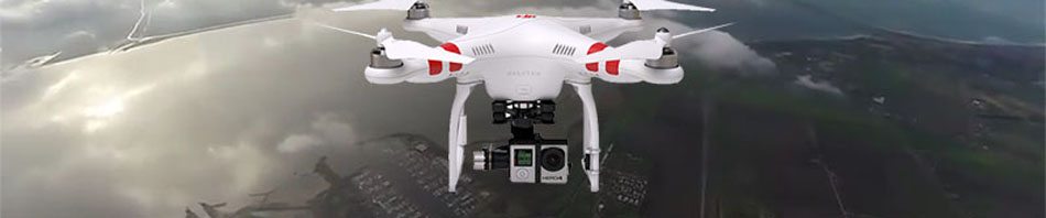
Surveying & Geoinformatics
Our Survey and Geotechnical departments strive to provide the most accurate and detailed data required by the Engineers in various projects, such as highways, railways, irrigation, etc. Reliable information is our most important product. Over decades, the company has built a strong goodwill among clients ranging from Government Organizations to private Corporate Houses. Our service offering includes
Before beginning a topographic survey, accuracy requirements and property characteristics, as well as clients desires, are considered to determine which method would be best. Our Total Stations provide input for our CAD systems, enabling direct digital mapping of topographic surveys and computer analysis of contours, slope, and quantities. Plotting is done on grid sheets, generally, in the scale of 1:500 or as specified by the client.
 View / Download Image for Plane Table Survey
Contour survey is carried out by observing spot levels at 15, 10, 5 m. grid or as per the client's specification. They are plotted on the drawings and the contours are drawn using the AutoCIVIL or Auto Plotter Software. Contours are interpolated at 0.5, 1.0, 2.0 m. interval or as specified by the clients. Generally, additional levels are taken to show the exact profile of the land.
Generally longitudinal levels are taken at 15, 20, 25 m. interval as specified and crosssectional levels are taken to cover the proposed width of the road channel railway line to access the quantity of earthwork to be done.
The vertical and horizontal profiles are designed by various programs written in Autolisp. The various alternatives can be run in computer for various profiles. Further the plane table details are collected to cover the required width.
The levels are taken in such a way that the profile could be drawn to measure ground clearance required by sag template. Plane table details for about 15 m. on either side of alignment are collected. This work is done to suit requirements for erecting towers and other structures.
View / Download Image for Transmission Line Survey
- Topographical (Land/Contour) Survey
- Hydrographic Survey
- Marine Survey
- Cadastral Survey
- Route Survey for Road, Railway Lines, Transmissions Lines, Pipe lines, etc
Plane Table Survey
The plane table survey is conducted to collect all salient features above the ground such as bridges, roads, drains, water hydrants, electric poles, telephone poles, factory, buildings, temples, schools, sheds, transmission line towers, culverts, major trees, field bunds, local humps, depressions, ponds, railway lines etc., which are shown at their exact position. The symbols representing these features are constantly refined to better relate to the features they represent, improve the appearance or readability of the map, or to reduce production cost.Before beginning a topographic survey, accuracy requirements and property characteristics, as well as clients desires, are considered to determine which method would be best. Our Total Stations provide input for our CAD systems, enabling direct digital mapping of topographic surveys and computer analysis of contours, slope, and quantities. Plotting is done on grid sheets, generally, in the scale of 1:500 or as specified by the client.
 View / Download Image for Plane Table Survey
Contour Survey
Contours are imaginary lines that join points of equal elevation on the surface of the land above or below a reference surface such as mean sea level. Contours make it possible to measure the height of mountains, depths of the ocean bottom, and steepness of slopes.Contour survey is carried out by observing spot levels at 15, 10, 5 m. grid or as per the client's specification. They are plotted on the drawings and the contours are drawn using the AutoCIVIL or Auto Plotter Software. Contours are interpolated at 0.5, 1.0, 2.0 m. interval or as specified by the clients. Generally, additional levels are taken to show the exact profile of the land.
Hydrographic Survey
General flow and soundings are measured with the use of the motorboat in rivers, creeks and sea. We are equipped with instruments like Water Current Meter and Echo Sounder. Water-Current Meters for measuring velocity and flow are calibrated in Central Water and Power Research Center at Khadakwasla, Pune.Road, Railway Line, Pipe Line, Channel & Nallah Survey
The preliminary traversing is done along the proposed route; various alternatives are checked to get most suitable alignment.Generally longitudinal levels are taken at 15, 20, 25 m. interval as specified and crosssectional levels are taken to cover the proposed width of the road channel railway line to access the quantity of earthwork to be done.
The vertical and horizontal profiles are designed by various programs written in Autolisp. The various alternatives can be run in computer for various profiles. Further the plane table details are collected to cover the required width.
Transmission Line Survey
Transmission line survey is done by Traversing and by Tachometric Survey. The alignment is generally proposed to avoid the villages, habitations & crossing of railway, highway and old high-tension lines. If the crossings are unavoidable they are crossed at about 90 degrees. The line should be straight as far as possible. Generally the suspension towers are proposed for straight portion or up to 3-degree defection, after every 10 towers one tension tower is proposed. The tension tower is proposed at the turning points having deflection from 2 to 45 degree of the alignment. Special towers are proposed at vital points like railway, highway and major river crossings.The levels are taken in such a way that the profile could be drawn to measure ground clearance required by sag template. Plane table details for about 15 m. on either side of alignment are collected. This work is done to suit requirements for erecting towers and other structures.
 View / Download Image for Transmission Line Survey